In many welding and cutting processes, gas is used as a source of energy, or to protect (shield) hot metal and electrodes from the atmosphere. Wherever gas is used, there is a need to control or monitor the amount that is used. In gas welding and cutting, it is the gas pressure that is controlled (Fig 1); where shielding is required, the flow is controlled (Fig 2). In both cases, a pressure reducing regulator is used and where flow is important, that is followed by a flow measuring device.
Properties of a Flow Meter
The choice of flowmeter can have a significant effect on the task at hand; whether that be in arc welding, medicine or another field. Flowmeter properties to consider include the following.
Flow Regulation
All of the flow meters considered here use a pressure reducing regulator in combination with a flow measuring device. Often, a single stage regulator is used, but a dual stage regulator, the equivalent of two single stage regulators one after the other, can be used in its place. The type selected depends on the requirements.
A dual stage regulator will significantly reduce supply pressure effect (SPE) at the expense of droop (a drop in pressure as the flow increases). SPE causes the output pressure of a regulator to increase as the cylinder pressure falls (as the cylinder empties). This, in turn, causes the flow to increase beyond its initial set point.
If the pressure of the shielding gas changes significantly in a single shift, such as a cylinder being emptied or a cylinder in a bank being changed, the use of a single stage regulator will require multiple flow adjustments. The use of a dual stage regulator will overcome this requirement.
Multiple regulator stages do not otherwise affect the operation or function of the regulator-flowmeter.
Pressure Compensation
In this context, pressure compensation involves the use of a pressure reducing regulator to set a high intermediate pressure to overcome any back pressure caused by minor torch nozzle blockages or from a long torch cable becoming twisted. Typically, this intermediate pressure is between 25 and 50 psi, but it could be as high as 80 psi (Fig 3).
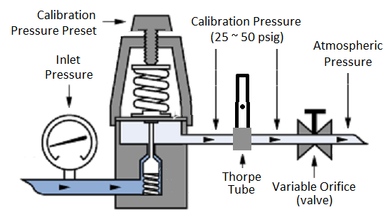
Pressure compensation makes the gas flow independent of any torch back pressure (blockages). Because of the high calibration pressure, it also causes gas surge which can be the cause of significant gas wastage and poor weld starts.
An uncompensated flow meter is sensitive to back pressure in the torch cable. Any back pressure causes reduced gas flow leading to improper shielding and potential weld defects.
Gas Surge
Gas surge is a rush of gas from a TIG or MIG torch when the trigger is pulled. The initial rush can be at several times the required flow rate, before it settles down to the value set by the flow meter. Gas surge happens because of the high intermediate pressure used in some flow meters.
Display Of Flow
Because of the way gauge type flow meters operate, they do not always display gas flow correctly. When the trigger is released, welding stops and the gas flow stops. A gauge type flow meter will not display zero flow. In fact, the indicated flow will increase because of the rise of pressure in the delivery hose.
Any torch back pressure in an uncompensated flow meter causes reduced gas flow leading to improper shielding and potential weld defects. In the case of a gauge type flow meter, the indicated flow remains the same, or may even rise, so the operator will be unaware of the reduced shielding.
Types of Flow Meter
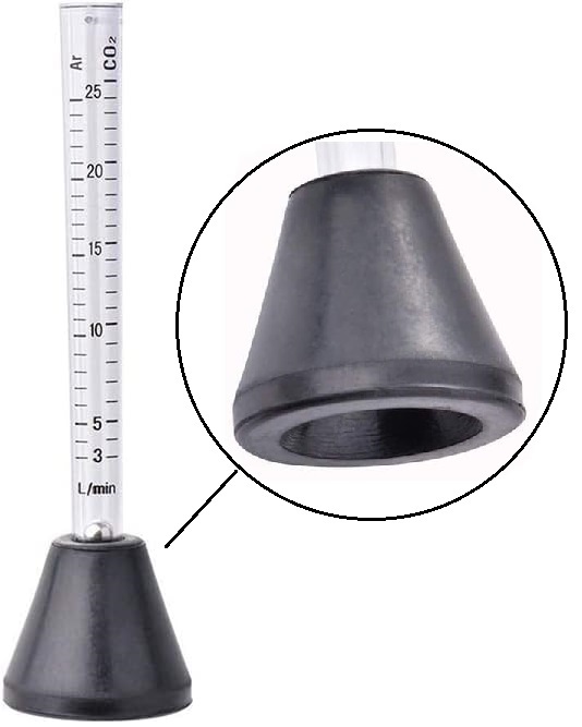
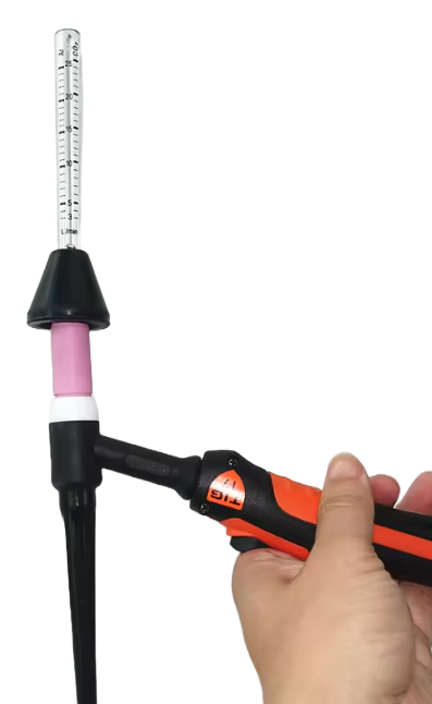
Flow meters measure the volume of gas being used per unit time in units of flow, such as litres per minute (L/m). There are many types and variations of flow meter, but in gas shielded arc welding, they are usually one of three types:
- variable pressure – fixed orifice,
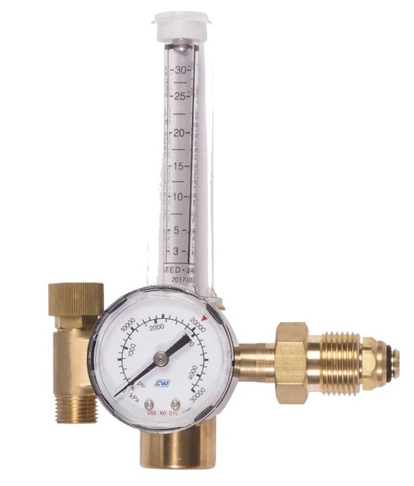
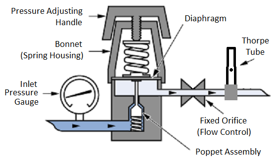
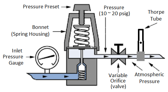
- variable orifice – fixed pressure and,
- specialised flow meters designed to reduce gas surge.
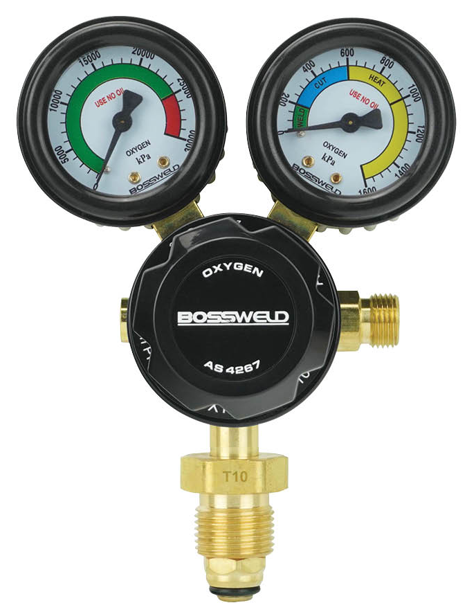
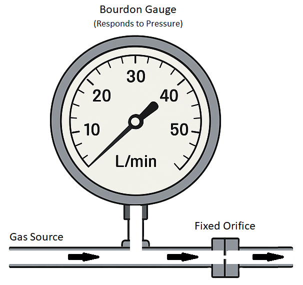
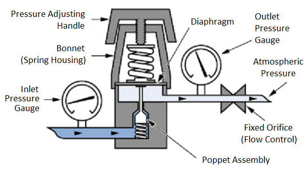
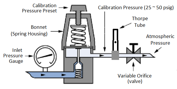
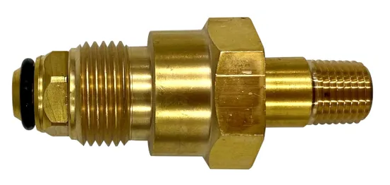
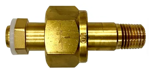
Variable Pressure, Fixed Orifice (VPFO)
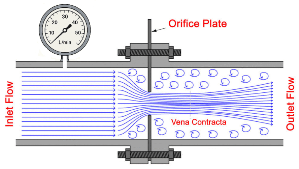
These use an adjustable regulator and a fixed orifice. The fixed orifice is placed at the output and as the pressure is increased, more gas flows through the orifice because of the increasing pressure differential.
The range of pressure needed to set the required flow depends on the size of the fixed orifice. If the orifice is small, the pressure must be higher, improving back pressure immunity but increasing the potential for gas surge in the process. The reverse is true if the orifice is larger.
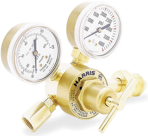
Variable Pressure, Fixed Orifice Using a Flowgauge (VPFO-G)
A regulator-flowgauge uses two Bourdon gauges, one displays the pressure of the gas supply (cylinder contents or manifold pressure) and the other is used, in conjunction with a calibrated fixed orifice, to measure flow.
The gauge above (Fig 5) measures the back pressure created by a restriction (fixed orifice) and this gives an indirect indication of the flow through the restriction. The dial is calibrated in units of flow rather than pressure.
A VPFO-G consists of a pressure reducing regulator followed by a calibrated fixed orifice (Fig 6). As the pressure is changed, the flow through the orifice changes. The outlet Bourdon gauge is calibrated to measure flow. It is a simple and indirect method, often used in welding and gas distribution systems to monitor flow.
The flow indication is only valid while there is flow. When the flow stops (not welding), the flow indication does not show zero. In fact, the flow indication increases because of the pressure buildup in the delivery hose prior to the gas solenoid in the welding machine. The flow can be set when the trigger is pulled and the gas is flowing.
Variable Pressure, Fixed Orifice Using a Flowmeter (VPFO-M)
The VPFO-M works in the same way as the VPFO-G just described. The difference is that the recalibrated Bourdon gauge is gone and a Thorpe Tube flow meter has been fitted after the fixed orifice to indicate flow (Fig 8). In this case, flow is only indicated when there is actual flow.
It consists of a pressure reducing regulator followed by a calibrated fixed orifice and then a Thorpe tube flowmeter. As the pressure is changed, the flow through the orifice changes as before and the actual flow is shown on the flowmeter.
Variable Orifice – Fixed Pressure (VOFP)
This type of flowmeter uses a factory set pressure reducing regulator (fixed pressure) and an adjustable valve (variable orifice) to set the flow.
These are generally configured with the valve at the outlet (pressure compensated), but some have the valve between the regulator and the flowmeter (uncompensated).
The compensated meter (VOFP-C) is typically calibrated at between 25 and 50psi and is largely independent of back pressure from the torch. That pressure also fills the gas delivery hose when welding stops. It is released with a surge when welding resumes.
For the uncompensated meter (VOFP-U), the Thorpe Tube is calibrated at atmospheric pressure (zero psig) (Fig 11). There is still pressure behind the valve so there is still gas surge, but less than the compensated meter because of the generally lower static pressure.
In both cases, these flow meters indicate zero flow when the flow stops.
Specialised Flow Meters
These are less common, special purpose flow meters that are designed to limit the delivery pressure and therefore limit gas surge. They include two stage regulator-flowmeters that are largely independent of the gas cylinder pressure, and digital meters that are able to adaptively adjust gas flow to the current need in real time.
These will be covered in the Gas Surge article.
Comparison Of Flow Meters
Regulator-flowgauge | Regulator-flowmeter | Regulator-flowmeter |
VPFO-G | VPFO-M | FPVO-C |
Variable pressure, fixed orifice – gauge | Variable pressure, fixed orifice – meter | Fixed pressure, variable orifice |
Zero compensated | Zero compensated | Compensated |
Always indicates | Indicates flow | Indicates flow |
Mount in any position | Mount vertical only | Mount vertical only |
More robust | Susceptible to damage | Susceptible to damage |
More accurate | Less accurate | Less accurate |
Less gas surge | Less gas surge | More gas surge |
Test Flowmeter
If there is any question about the shielding gas flow at the torch, a test flowmeter can be used to check it.
The test gauge consists of an uncompensated (calibrated at zero psig) Thorpe tube flowmeter with a tapered rubber connection on the bottom. To test the gas flow:
- point the nozzle of the torch up,
- place the rubber connection over the nozzle,
- For MIG, release the wire feed tension,
- pull the trigger and
- ensuring that the flowmeter is vertical, read the flow from the scale.
Flow Meter Selection
There is no single flow meter that will serve every application. Selection involves determining what is important on your job, and selecting appropriately.
Property | Pro | Con |
Dual Stage Regulator | More stable flow when source gas pressure changes due to high usage or from cylinder changes in a bank | Higher cost |
Pressure Compensation | Gas flow is largely independent of back pressure in the torch cable caused by partial blockages or twisting | Increased gas surge leading to increased gas costs and potentially poor weld starts |
Flowgauge (Bourdon gauge) | Simple, robust, accurate and can be mounted at any angle | Does not show zero flow and is sensitive to back pressure causing reduced flow which is not evident to the operator |
Flowmeter (Thorpe tube) | Easy to read, clearly indicates zero gas flow, shows the actual gas flow even with significant back pressure | Must be mounted vertically and is more susceptible to damage |
In addition, regulator-flowmeters are available with vertical mount and side mount. Make sure your selected meter can be mounted properly – Thorpe tubes must be mounted vertically.
Argon and argon mixes use a T10 cylinder connection, carbon dioxide uses a T30. Most flow meters come with a T10 connection, so an adaptor may be required. The regulator-flowmeter stem can also be replaced but be sure to get the correct regulator thread. Often these are 1/4″ NPT rather than the standard 1/4″ BSP.
