
What is gas surge?
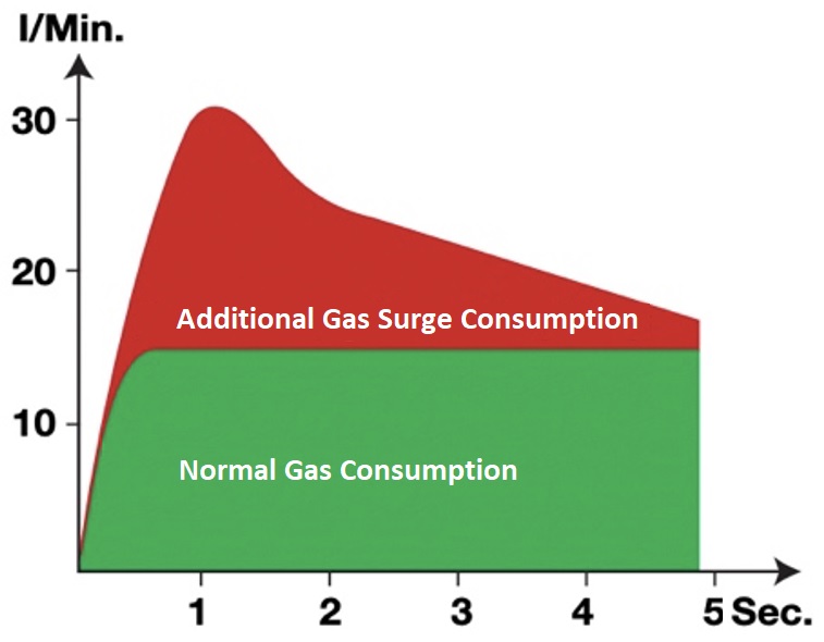
Gas surge is a rush of gas from a TIG or MIG torch when the trigger is pulled. The initial rush can be several times the required flow rate, before settles down to the value set by the flow meter.
The consequences of gas surge
There are three issues that are caused by gas surge.
- Wasted gas. The surge happens every time the trigger is pulled and if there is a lot of stop-start welding, the amount of gas lost can be high, and that costs money.
- Loss of shielding. The gas flow rate during the surge is several times that required for shielding and that can cause turbulence and draw air into the gas flow. This may result in weld defects such as porosity, and poor weld starts.
- Distraction. Some welders simply find the gas surge annoying.
For an individual welder, none of these issues may be important, but in an industrial setting, where there are several welders and standards to be met, they can be significant. Manufacturers of devices to mitigate gas surge routinely claim a 50% saving in shielding gas.
The cause of gas surge
Gas surge is caused by a build-up of gas pressure in the delivery hose between the regulator-flowmeter and the welding machine’s gas solenoid when not welding. The amount of gas that accumulates depends on the type of flowmeter in use. A pressure compensated flowmeter will accumulate much more gas than many uncompensated flowmeters because of the high calibration pressure used. In either case, when the trigger is released, gas pressure will increase in the delivery hose.
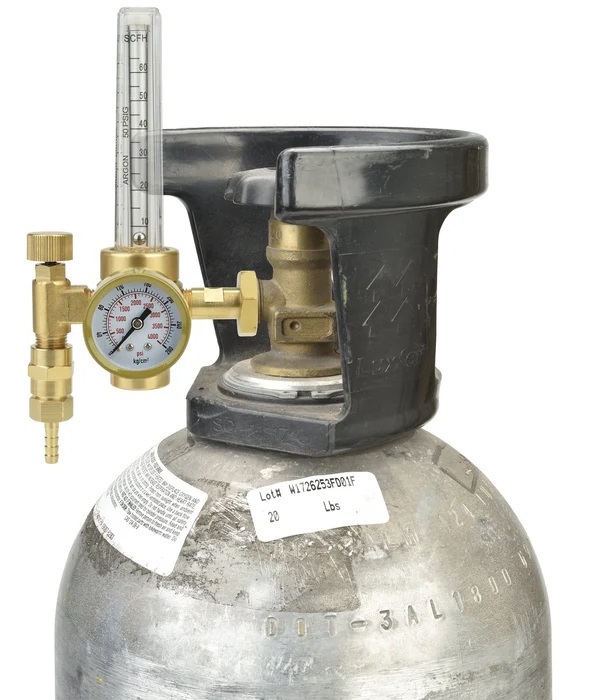
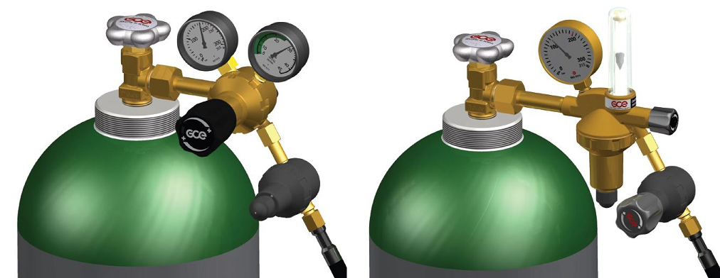
The pressure compensated regulator-flowmeter shown here reduces the cylinder pressure (say 2000 psi) to a working pressure of 50 psi for the flow meter. The knob operates a needle valve to adjust the flow which is indicated on the Thorpe Tube flow meter.
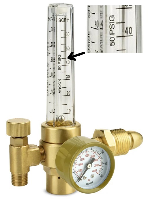
During welding, the shielding gas flows from the flowmeter at the required rate – say 10 L/m or 20 CFH. The gas pressure in the hose between the flowmeter and the torch will be about 4 psi.
When the trigger is released, the gas solenoid in the welding machine stops the gas flow and the pressure in the gas hose between the flowmeter and the gas solenoid increases to 50 psi – the calibration pressure of the flow meter. Depending on the gas hose, it will likely expand because of the increased pressure and so holds more gas.
If an uncompensated flowmeter were used, the pressure would build up, but it would remain low – generally less than for a pressure compensated flowmeter.
When the trigger is pulled to resume welding, this pressurised gas contained on the gas hose is released in a sudden rush causing a gas surge.
Reducing gas surge
Gas surge is caused by the volume and pressure of the gas stored in the gas hose between the flowmeter and the gas solenoid when the trigger is off. Clearly then, one approach to reducing gas surge, is to reduce the volume of the hose where the gas accumulates, or the pressure at which it is stored – or both.
Another approach is to use a digital flow meter. It uses a closed loop control algorithm to vary the flow based on the measured flow and the pre-programmed job requirements.
Reducing Volume
The volume of the hose is reduced by:
- Using only the length that is needed,
- Using only the inside diameter that is required for proper gas flow and
- Using a reinforced gas hose that does not expand significantly with pressure
Reducing Pressure
Pressure directly affects the volume of gas within a container. Using the ideal gas law, the relationship between volumes of gas at different pressures can be determined.
Vout = Vin * (Pin / Pout)
Where:
Vin = Volume in the hose
Pin = Pressure in the hose
Vout = Volume of gas at the outlet
Pout = Pressure at the outlet
The pressure in the hose is 50 psi (using the example above) and the pressure at the outlet is 4 psi so (using absolute pressure):
Vout = 3.4 * Vin
If the calibration pressure of the flowmeter could be halved, expansion of the gas would be halved and so would the gas surge.
Note that some would simply reduce the preset pressure of any compensated flowmeter. That will reduce gas surge, but the flowmeter will no longer be calibrated. That might not matter to you but be aware that reducing the calibration pressure from say 50 psi to 25 psi will cause the flowmeter to read about 24% high, much reducing the gas coverage.
Another approach to reducing the gas pressure is to use an uncompensated flowmeter. In this case gas surge is reduced but at the expense of a higher sensitivity to back pressure from the torch.
Using a Digital Flowmeter
A digital flow meter uses a different approach to regulating gas flow. Instead of using a Bourdon gauge or a Thorpe tube for flow measurement and display, a closed loop control system is used (sometimes called digital gas control (DGC)). Digital flow meters are typically contained within the welding machine, replace the usual gas solenoid and are controlled by software.
Instead of a standard on-off solenoid valve, digital flow meters use a proportional flow valve that provides variable control. The proportional control mechanism uses sensors to determine the gas flow and then, if necessary, makes adjustments to correct the flow. The ESAB DGC system incorporates two sensors, a differential pressure sensor to regulate gas flow rate in litres per minute and an absolute pressure sensor that is used to determine the mass flow rate. This results in the ability to rapidly and accurately control gas flow, no matter the type of gas being used.
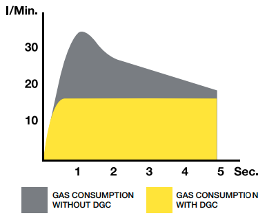
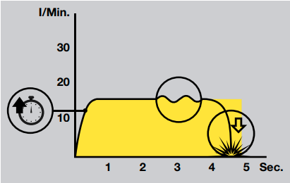
The following graph shows how ESAB digital gas control reaches the set flow rate quickly and stabilises immediately. Conversely, a conventional compensated flow meter overshoots significantly because of gas surge, and then takes additional time to reach the set value. With short gas hoses, it can take 2 to 3 seconds; with a 40m hose, it can take 10 seconds or more to reach the set value.
In addition to the complete removal of gas surge, there are additional benefits of using a digital flow meter. They:
- Regulate flow to the correct rate independent of cylinder pressure which preserves gas shielding and therefore weld integrity as cylinders run low. A dual stage regulator is no longer needed to achieve this.
- Regulate flow to the correct rate independent of gas flow restrictions, which also preserves weld integrity. A compensated flow meter is no longer needed to achieve this.
- Eliminate the need to set the flow rate upon first use. Once the flow rate parameter is set, it remains until changed.
- Eliminate the need to reset the flow rate when changing torches or changing gas mixes.
- Detect flow variations from the set value and terminate the weld in a controlled manner.
- Detect a total loss of pressure (e.g., the gas hose becomes disconnected), and terminate the weld immediately.
- Can be controlled by the welding machine’s synergic algorithms to change the gas flow with welding current, base material or other factors based on a welding procedure.
The ability to detect pressure loss and flow variations helps to avoid porosity issues, as summarized in the following illustration.
Summary
Gas surge can be reduced by minimising the volume of the gas hose (shorter, smaller inside diameter and reinforced to prevent expansion), by using a compensated flowmeter with a lower calibration pressure (reduce pressure to say 20 or 25 psi or use zero compensation), or by using a digital flowmeter to control flow in real time.
Commercial gas surge mitigation (Gas Economisers)
To reduce gas surge, most manufacturers use either:
- the volume, pressure and orifice approach as outlined above, or
- a zero compensation approach, or
- an additional regulator at the output of the existing flowmeter to reduce the delivery pressure (resulting in zero compensation) or
- a digital flow meter.
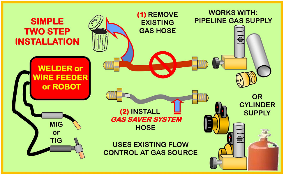
WA Technology – Minimises Volume
This company sells a system based on minimising the volume of gas that can accumulate. It uses hoses that are only as long as needed, have a small inside diameter and are reinforced to reduce expansion. In addition, a fixed orifice is used to limit the maximum flow.
Concoa – Zero Compensation
CONCOA’s Gas-Saver technology couples a non-compensated flowmeter to an adjustable regulator. The operator adjusts the regulator pressure while observing the flow on the flowmeter scale. The flowmeter accurately displays the gas flow rate, even when the regulator is adjusted to as low as 3 or 4 psi. This in turn minimizes the static pressure buildup in the hose.
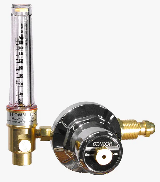
Concoa 6590 Series Flowmeter Regulator
The flowmeter shown is the tamper proof Concoa 6590 Series Flowmeter Regulator with optional gas saver functionality. Once the required flow is set, it is locked preventing unwanted (and unauthorised) changes that might increase the flow unnecessarily.
As this is an uncompensated design, gas surge is reduced at the expense of an increased sensitivity to back pressure from the torch.
GasiQ’s Optimator
The GasiQ’s Optimator is a self-contained solution that uses a second regulator to limit the pressure in the hose.
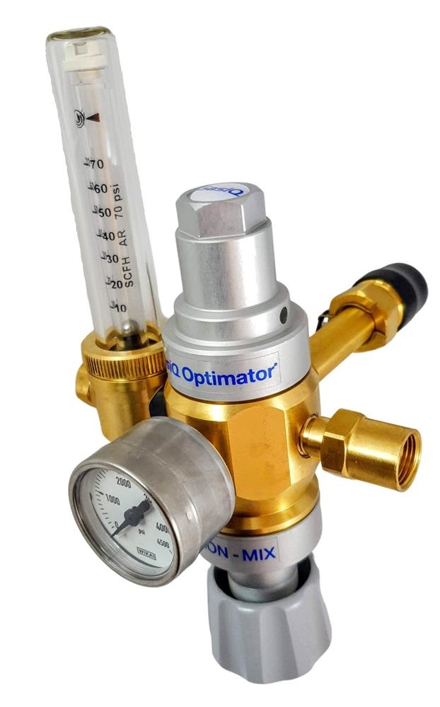
The company claims:
The GasIQ Optimator® is a high performance dual stage regulator with an in-built economizer and meter to gauge flow. It is mainly used for advanced gas shielded welding production applications, where it will reduce the total welding cost by decreasing the gas consumption by up to 50%. In addition, reduced porosity sensitivity improves weld quality. Tests have shown that Volvo saves at least 43% gas through the installation of Optimator®. |
The GasIQ Optimator® is configured as a standard regulator-flowmeter calibrated at a quite high 70 psi, followed by an adjustable regulator to control the delivery pressure in place of the normal adjustable valve.
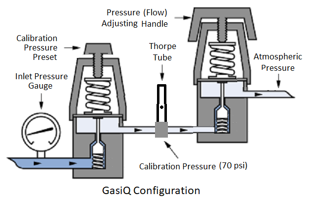
The second regulator is used to set the flow and keeps the delivery pressure low (3 to 15 psi) resulting in an uncompensated flowmeter.
In addition to a reduction in gas surge because of the low delivery pressure, this configuration has the advantage of dual regulators in reducing supply pressure effect.
There are other manufacturers of gas economisers that are of the same configuration as the rather expensive ($300) GasIQ Optimator®. Some examples are listed below.
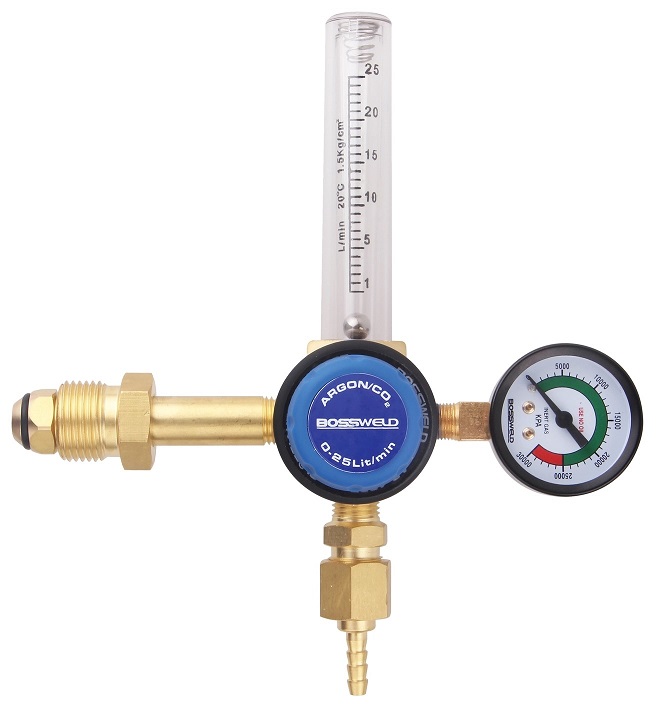
Bossweld flow meter – $95
This consists of a preset gas regulator followed by a flow meter with the flow set by a second regulator following the flow meter. The configuration is identical to the GasIQ except that the intermediate calibration pressure is reduced to 21 psi.
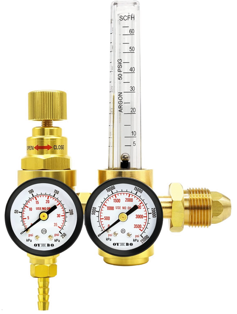
OYHBO flow meter – $88.
This is a preset gas regulator followed by a flow meter with the flow set by a second regulator following the flow meter. A second pressure gauge monitors the delivery pressure. The configuration is identical to the GasIQ except for the additional pressure gauge and the intermediate calibration pressure is reduced to 50 psi.
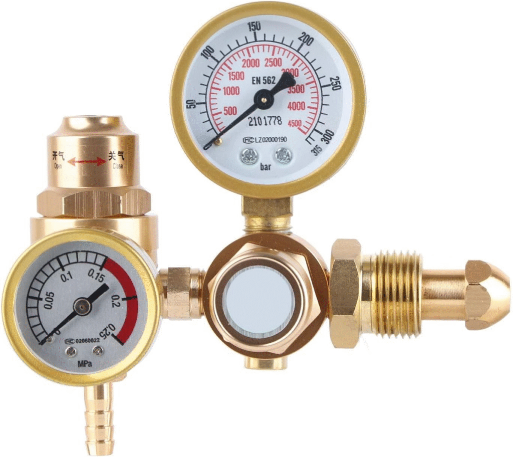
Mingzhe flow meter – $45
This is similar to the OYHBO flow meter. It consists of a preset gas regulator followed by a second regulator to adjust the flow. A second pressure gauge monitors the delivery pressure. There is no flow meter, just the pressure gauge.
The same result can be obtained by using a standard regulator-flowmeter and fitting an additional regulator to its output. The flow control valve should be fully open and the flow is adjusted with the second regulator. An air pressure regulator could be used for this purpose or one of the regulator-economisers shown below.
Regulator-economisers
Several manufacturers produce devices which are simply a pressure regulator to be mounted at the output of a standard regulator-flowmeter. These are designed to limit the delivery pressure and, in so doing, reduce gas surge.
Here are two examples:
GCE GS40
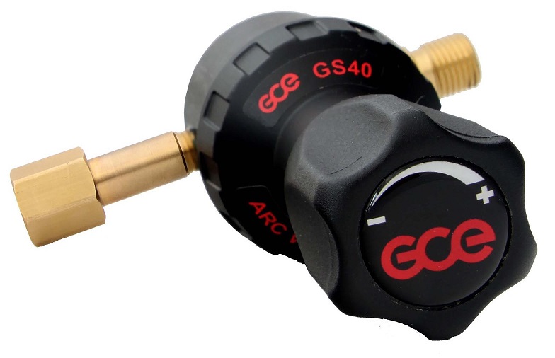
Manufacturer’s claim:
When you close the gas flow at common pressure regulator during the welding process interruption, the outlet pressure in the connecting hose rises up much above the optimal level (acc. to ISO 2503 up to 30%). Then the volume of the gas, higher than really needed, is blowing through the system after the welding process starts again by switching on the arc on the welding torch. GS40 minimises amount of such waste gas accumulated in the connecting hose. The optimal, predefined gas flow is delivered to the welding process during all its phases. Adjustable variant with the handwheel (GS40A) is to be used with regulators with flow-meter, fixed variant (GS40F) with regulators with litre-scaled pressure gauge.
Harris Inert Gas Guard
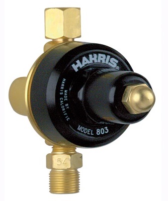
Manufacturer’s claim:
Harris Inert Gas Guards are designed to save shielding gases by reducing the gas surge when a MIG gun or TIG torch is activated. Because they are designed to reduce the pressure held in supply hose, gas waste is reduced when the gun or torch is triggered. They save shielding gases also by delivering a controlled flow rate. Operators will typically set shielding gas flow rates higher than necessary for a welding operation. Once set by a supervisor, the Inert Gas Guard delivers the precise amount of flow for the operation, eliminating the needless waste of gas.
Digital Flow Meter
Electronic monitoring and recording has been used for some time to verify that work has been carried out according to the welding specifications. Some examples are:
- Lincoln Electric – CWT® GFM™, Gas Flow Monitor
- Welding Automation – Gas Tracker optimisation Gas Flow Monitor
- Wire Wizard – Portable Gas Flow Monitor
Digital flow meters are a major step forward where the flow is not just measured and (potentially) recorded, it is controlled in real time.
Digital flow meters are typically integrated into the welding machine by manufacturers such as ESAB, Fronius and EWM but are also available an external add-ons from manufacturers such as Abicor Binzel.
These products can be seen at the following links:
• ESAB – TruFlow Digital Gas Control
• Fronius – The intelligent gas controller
• EWM – The digital gas control valve (DGC)
• Abicor Binzel – Electronic Welding Regulator (EWR)